

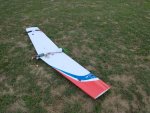
My Prandtl-D build Journey from Simple Dollar Store Poster Board

Over the previous two years many others have managed creating various forms of this craft as a glider or a 3d printed plane and been successful.
What I learned about the PRANDTL wing.
This passion all began when the PRANDTL wing as featured on an FTCC when they spoke with NASA engineer. The one that flies with *proverse* Yaw. This is Yaw that produces an axial forward thrust in the direction of the turn. in Short it creates coordinated turning.
[MEDIA=youtube]FC6WSo2grNs[/MEDIA]
I looking into it here: http://www.amaflightschool.org/PRANDTL and https://www.nasa.gov/centers/armstrong/news/FactSheets/FS-106-AFRC.html
and of course the link of the nasa site showing the summer inters building a fiberglass one.
and looked through the White paper from NASA.
From the White Paper:
There is enough information there for anyone to build this sucker. and the AMA site as the IGS files (whatever they are)
but I took the paper coordinates and ploted it in EXCEL xy graph. and got this:

I’ll continue working on the wingtip section…
4/29/19 Edit:

as you can see it is symmetrical.
Then they have a table describing the Wing’s twist over the wing length broken into 20 sections. 0 is the base 20 is the wingtip

 <-Wing Tip Config from AMA site
With a 12.3 ft Wing Span, The base is chord 15.75″ and 3.94″ tip chord, with a 2.5° dihedral, with a 24° sweep (<- edit 4/29/19)
I think I will make mine 9ft. that will make each half 4.5 ft and should fit in my Toyota Yaris Trunk.

Using this knowledge and some novel building ideas spawned from building a Mara Foam Board build modeled from the balsa techniques. The finished product had me excited. so much, that I tried a glide off the front porch in the dark. After a promising attempt that never saw evidenciary succes, It
Through the Aviation RC Noob Podcast, Joe and I have chanced to have a great interview with Red Jensen (Episode 25, Episode 26) who was a chief pilot over much of the Prandlt-D project headed by Chief Engineer Albion Bowers. As we prepared for the interview, and doing research about the Neil Armstrong Research Center I saw different versions so I took a moment to create a simple modification of the plane to change the planform, but not the other key elements. And simplify it so it can be built using fold-over techniques.
2-sheets – nearly no waste
This new plane design is two un-wasted sheets of Dollar tree foam board, cut longways from 8″ to 12″ from one side. Then cut off a 1/2 strip from both sides. To build a spar. This allows the construction of the wing half.
The important piece to this puzzle. is how to Place the spar, and how to shape the trailing edges of the wing halves. It is important that the inner section functions like a modified Clark Y, and the outer like a Symmetrical wing, with a twist from +8° AoA on the inner section, and it twist to a -2° AoA at the tips.

Spar line
The spar line on the bottom of the wing should be from ##” to ##” at the wingtip

On the top it must be moved back a 1/4″ on the wing root and remain at ##” at the wingtip.
Trailing Edge
Outer edges
The trailing edge treatment is also important. the outer half must bevel the edge in 1″ from the trailing edge insides, top and bottom.
Inner Edge
The top must have the trailing edge beveled 1″ in along the inside trailing edge, like the outer half.
The bottom of the must have a 1″ bevel on the outer side of the trailing edge (not the inside), opposite the outer wing half.

Glue-up
The last key bit is the trailing edge of the root half top sits on the bottom ~1/2 to 1/4″ from the TE. and fairly constant for the inner half of the wing. this then transitions to matching trailing edges for the outermost wing quarter to the tip.
The key to this and getting the twist, is to put the wing flat, place a ruler under the trailing and lift the Wingtip 1 3/8″ at the tip TE, while keeping the front tight against the build surface with weights. (such as bean bags, rice, or shot), It is VERY important to let the glued cool completely before releasing the weights. (10 mins. min.)

Symmetry
Do the same but mirrored to the other side.
It is important the section is symmetrical airfoil at the tips and 10° angle from the table on BOTH WING HALVES.


Once completed the wings can be joined, and glued together. If you are concerned about strength, imbed a 10″ BBQ skewer in an 1/8″ wide track glued in directly over the spar. ensure glue setting before moving on (10 min.) and put a piece of tape from wingtip to wingtip.
Control surface should only be on the outer 1/8 to 1/4 of the wing. as this is where the twist coupled with surface deflection of a roll will yield the forward lift, and thereby the proverse yaw, which allows for no rudder.
Electronics Location
Once the body is build and the control surfaces are place. I used a 9g servo placed in front of the spar at the inner edge of the control surfaces.
The motor must be mounted at the back edge of the wing so to have a 10° with the top of the wing.

There is also and optional Battery and FPV pod to attach to the bottom front of this. [plans pending]


Weight
Base Weight: 230g

Dry weight: 360g
AUW: 645g
SPECS:
winspan – 60″
WingChord – 12″
Motor: 2306 1700kv Emax ECO
Esc: 35A 2-6S opto (with Separate BEC)
Prop: 6″x3″
Battery: 2200 mAh,
Ballast: 1300 mAh
2-9g Servo with 20″ leads


PLANS

Glide Test
Maiden Flight and Proof of Concept
[MEDIA=youtube]h9-TMqC_BB8[/MEDIA]A Graceful 2nd flight Video:
[MEDIA=youtube]keZ0fyUBuS4[/MEDIA]
Another Flight Video
[MEDIA=youtube]dV805AGUzPE[/MEDIA]